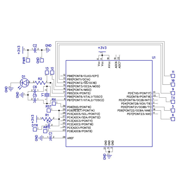
Control Board
The control board houses an ATMega328, the brains of the anklet. This board takes in commands via a serial line to the Bluetooth board and issues orders to the motor controllers via PWM. Check out the firmware on Github.
Get to the places that matter most
without the distractions
LeadMe's internals consist of a set of small circuit boards; a control board, a LiPo charging board, a motor driver board, and a Bluetooth communication board. The control board consists of an ATmega microcontroller, which uses the Bluetooth board to take in commands from the user's smartphone, and outputs control signals to the motor driver board, which actuates the vibrating motors on the anklet. Power for this system is provided by a Lithium Polymer battery, which is charged and discharged safely by the LiPo charging board.
LeadMe's internal electronics consist of four small circuit boards, each serving a distinct purpose. The boards are then cast directly into the silicone casing of the device.
The control board houses an ATMega328, the brains of the anklet. This board takes in commands via a serial line to the Bluetooth board and issues orders to the motor controllers via PWM. Check out the firmware on Github.

The motor board takes PWM signals from the control board and amplifies them with a FET to run the five motors in the anklet.

The power board interfaces with a Lithium Polymer battery, providing a USB port to power a LiPo charging IC and regulating power draw from the battery when the anklet is running.

The Bluetooth board handles communication with the phone, allowing commands to be sent across a serial line to the anklet.
Some of the major electronics components are listed here; see the schematics above for a full overview of components.
For the firmware source code, visit our GitHub repository.
For technical details, click here.